
Adding an internal GPS Disciplined Oscillator frequency reference to the Icom IC-9700
One problem recognized by many IC-9700 owners, especially on the 440MHz and 1296MHz bands, is a thermally-induced frequency drift that occurs whenever the cooling fan starts. Icom has partially addressed this issue with a table-driven temperature profile, but this does not work well when using very narrow-band digital modes, especially for EME or WSPR.
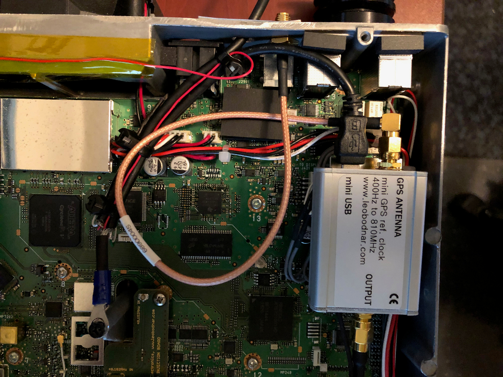
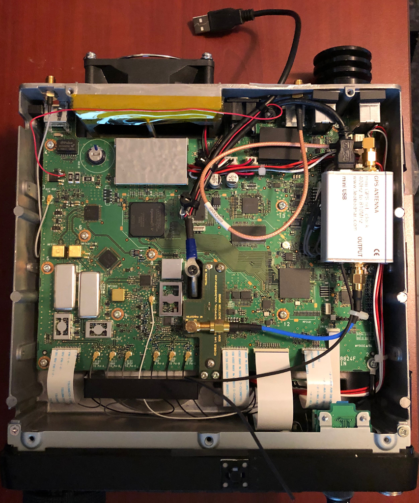
The photos shown here outline a solution that makes use of two components from Leo Bodnar Electronics in the UK. It involves a single-port GPS clock plus a specially designed coupler board for the IC-9700 that "swamps" the built-in TCXO chip and locks the radio to the 49.152000 MHz output of the GPS Disciplined Oscillator. This solution has proven to be rock solid and very effective. It results in the radio having a frequency accuracy of about 1 Hz at 1296 MHz. No thermal frequency drift has been observed when the cooling fan starts.
One important thing to note … the 5VDC line from the external USB cable is cut and power is tapped off a 5V regulator inside the radio as the only source. This avoids the problem of two different power supplies arguing with each other (and causing damage) when monitoring the GPS status via USB.
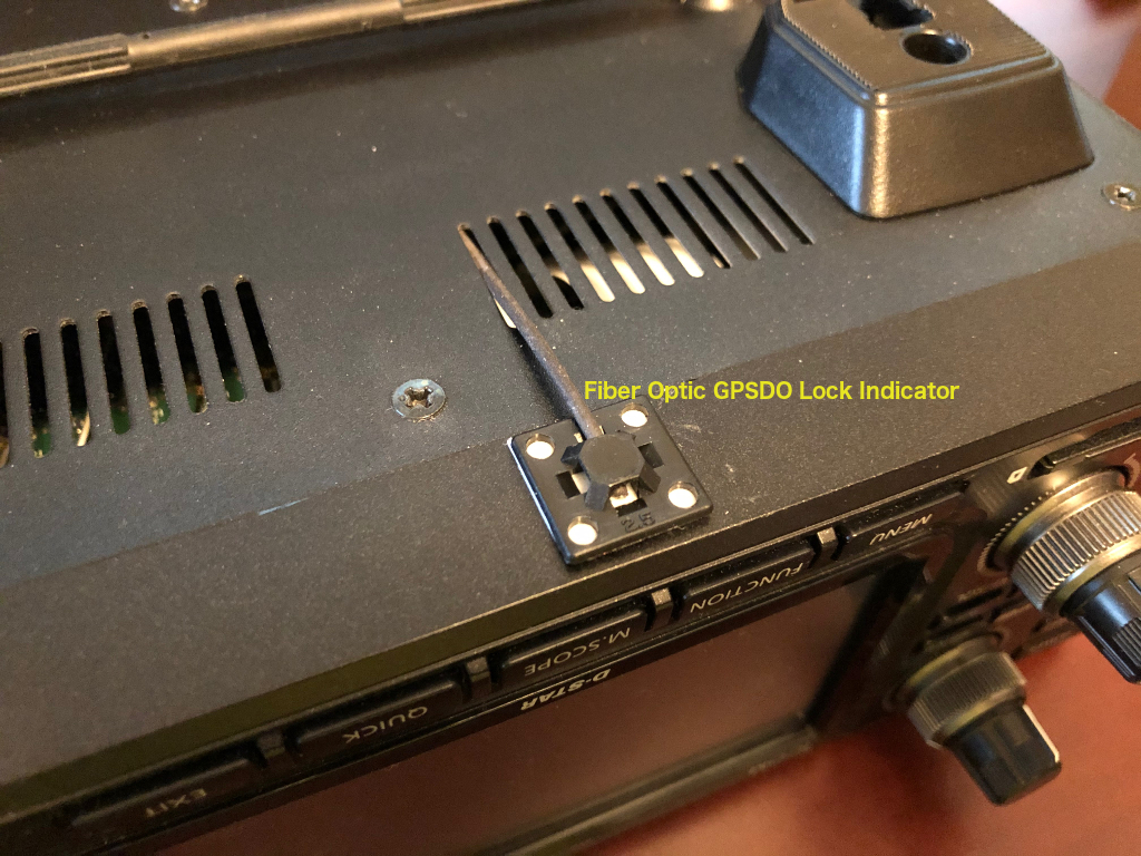
The GPS lock status LED is carried from the clock's enclosure to a location under the radio's front bezel by a fibre optic line that rests in a small mounting clip. It is a friction fit which allows easy removal and replacement of the fibre should it be necessary to remove the bottom half of the radio's case.
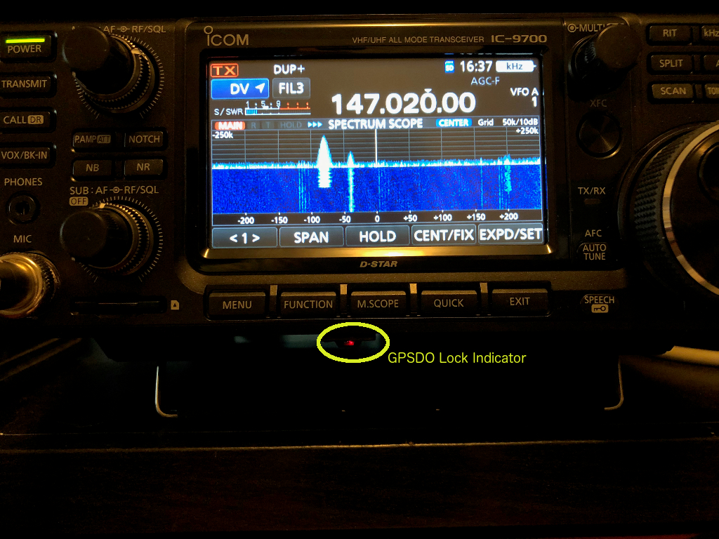
The GPS Lock LED blinks while the clock is acquiring satellite signals, and glows solid red when locked.
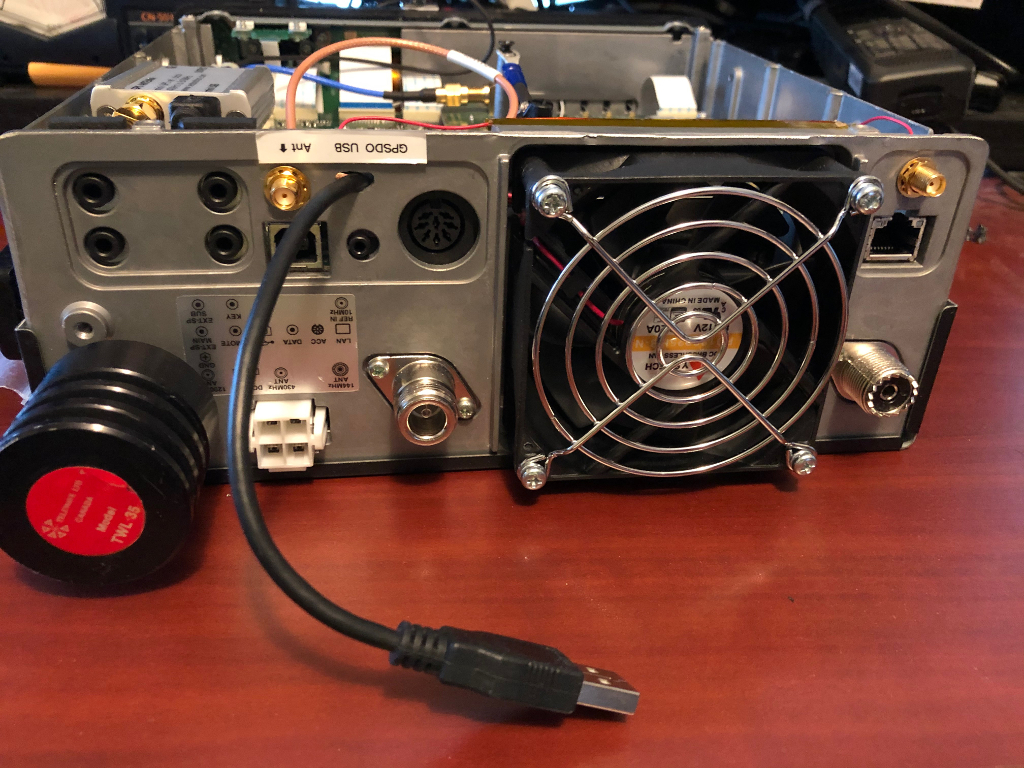
PLEASE NOTE !! Drilling the holes for the two extra connections must be done VERY carefully by masking off the inside of the entire radio to prevent metal crumbs from getting in where they could cause damage ! This modification is not for the faint of heart. You have been warned :-)
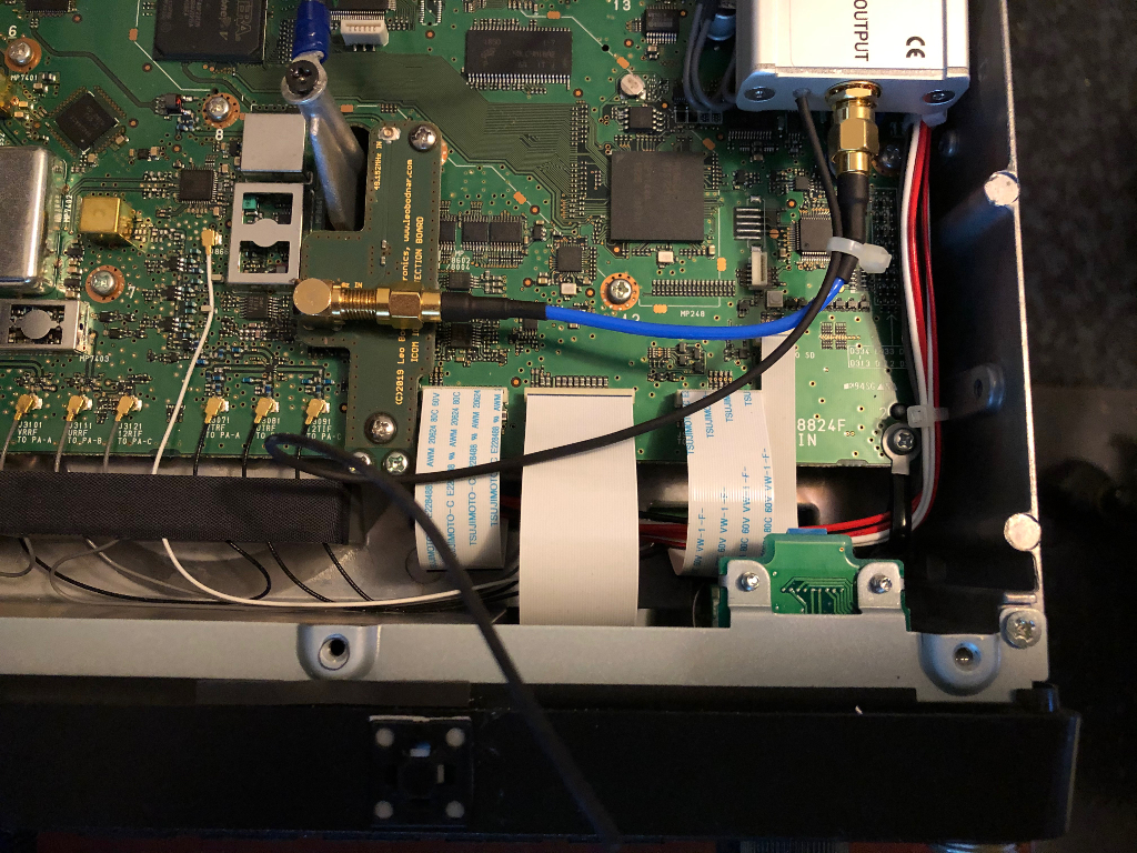
You can see the black-covered optical fiber that goes to the mount under the radio's front bezel. It is inserted into a 1 millimetre hole drilled into the plastic LED diffuser dome in the clock's case. The mount under the bottom edge of the radio bezel is just a standard cable tie adhesive anchor with the fiber loosely pushed through it.
For hams in Canada, Mike VE7HMW at Burnaby Radio is offering an installation service. Full disclosure … Mike and I worked on this project together, but I have no financial interest whatsoever in Burnaby Radio or the GPSDO installation service.
Page Visits